Ok so I took the time to search for this issue on the forums, with not much luck. This is the code Im getting from the ABS scanner. The truck is a 2001 2.2 flex fuel, manual transmission, disk brakes up front and drum on the rear.. My ABS light along with my brake light pops on and off at wierd times. Driving , stopping,etc... It gives me the 265 code "Electronic Brake Control Module Motor Relay Circuit". I was wondering if anyone else has had this issue and what you did to go about fixing it. Most of the post's I have seen have been about the sensors in the front of the wheels for the ABS. I have not seen anything for this particular code, that is unless i overlooked it. Any help will be gratefully appreciated. Thanks

ABS code # 265 Electronic Brake Control Module Motor relay Circuit?
code_red63366
Discussion starter
620 posts
·
Joined 2011
- Add to quote
Ok so I took the time to search for this issue on the forums, with not much luck. This is the code Im getting from the ABS scanner. The truck is a 2001 2.2 flex fuel, manual transmission, disk brakes up front and drum on the rear.. My ABS light along with my brake light pops on and off at wierd times. Driving , stopping,etc... It gives me the 265 code "Electronic Brake Control Module Motor Relay Circuit". I was wondering if anyone else has had this issue and what you did to go about fixing it. Most of the post's I have seen have been about the sensors in the front of the wheels for the ABS. I have not seen anything for this particular code, that is unless i overlooked it. Any help will be gratefully appreciated. Thanks
code_red63366
Discussion starter
620 posts
·
Joined 2011
Is there a link that supports ABS codes somewhere on the internet? Been doing alot of searching and not much luck.
59,755 posts
·
Joined 2006
means the ABS control module under hood has an issue with circut...i.e. sensor loosing connection..................mine does same thing
code_red63366
Discussion starter
620 posts
·
Joined 2011
Thanks S10dude. I will check out all the connections and mae sure there plugged in all the way.
code_red63366
Discussion starter
620 posts
·
Joined 2011
Hmmn,, well I took the time to remove both wheels today and clean/test both ABS sensors on my truck. They both checked out OK and cleaned (and NO I did not use brake cleaner on the sensors, but instead just cleaned them the old fashion way, with a rag, a tooth brushand and water.), I cleared the code and GUESS WHAT???? Still have the ABS problem, SOOOOOO its was not the sensors. NOTED*
834 posts
·
Joined 2007
Hmmn,, well I took the time to remove both wheels today and clean/test both ABS sensors on my truck. They both checked out OK and cleaned (and NO I did not use brake cleaner on the sensors, but instead just cleaned them the old fashion way, with a rag, a tooth brushand and water.), I cleared the code and GUESS WHAT???? Still have the ABS problem, SOOOOOO its was not the sensors. NOTED*
Make sure your Sensor Connector Harness(es) (should be a 3way harness) aren't torn and/or binding...there could be a short in the actual harnesses themselves, which would require installing new ones(splicing/soldering which is the best way to do electrical work then use the shrink tubing/conduit)! Next time use CRC Electrical parts cleaner non-flammable avail at any autoparts store! Good luck!
code_red63366
Discussion starter
620 posts
·
Joined 2011
Thanks GMCNoma, I did take the time to trace the wires up to the frame and check for that, all was good. I replaced these sensors when I 1st bought the truck, thinking that it was the fix yet abs light was still on. that's why I posted the exact code number and all, thinking I had a problem elsewhere besides the sensors ( I cannot see them going out after only 2 years). Next step will be the actual abs module on the drivers side fender.
5,092 posts
·
Joined 2010
The code is for the ABS relay. The bad news; the relay is in the ABS module. Probably gonna need a module replacement.
834 posts
·
Joined 2007
Yeah, knowning your luck it is the relay, but since your in there anyways theres no point in doing it half ass. You just might as well just replace the entire ABS Module (box), cause you dont know when that module could go or something else happen to it. Have your vin # ready Call you local Dealerships parts dept. and grab the part number for the ABS Module Assembley. Compare prices with OEHQ.COM , They do free shipping on orders over $75, and use Coupon/discount code OEHQ2011 (no spaces) at check out. Just stick with GM/AC-DELCO parts, just do more diagnostics to be sure it is the relay and inspect the ABS module assem. to make sure you arent gonna need anything else before installing a new one! Good Luck!
code_red63366
Discussion starter
620 posts
·
Joined 2011
Thanks for the responses here everyone.It was a huge help!!!
code_red63366
Discussion starter
620 posts
·
Joined 2011
Oh, I figured I would add this link for people who search for this thread code/issue. This link tells it all and can simply end up being a cheap fix ( I will see if it works out for me and reply, anyways here is the link:
http://www.automotivehelper.com/topic503743.htm
http://www.automotivehelper.com/topic503743.htm
157 posts
·
Joined 2010
Common relays have solenoids in them so I would say your code could be the same as mine. I hope you do check it out and see if you can fix yours the same way I fixed mine.
code_red63366
Discussion starter
620 posts
·
Joined 2011
Alan. i looked up the modulemaster website , yet didnt have much luck finding info on a repair manual for taking apart the ABS, Im guessing you may have talked to a tech? Or did I overlook it?
157 posts
·
Joined 2010
On the modulemaster you click as if you were going to send it to them where they show you how to remove it. Pretty much you just unplug the electric stuff, remove the 4 star screws, and pull the module off the hydraulic valve block. You should still be able to drive your truck without the module on it. That site also shows you which module unit you have to see if it is repairable. I hope you have the same one I have but I assume if you have an unrepairable one then you would have to buy a new one.
http://www.modulemaster.com/en/abs/kh325_310_30.php
http://www.modulemaster.com/en/abs/kh325_310_30.php
157 posts
·
Joined 2010
2,038 posts
·
Joined 2009
I had that code on my son's truck and got 1 from the S10 Warehouse for $30 shipped and it only had 11K miles on it, but that was about 3 years ago...Still works great
code_red63366
Discussion starter
620 posts
·
Joined 2011
30 bucks!! Darn,,, how do i miss things like that? Im gonna try alan's fix for 0 bucks... but will give them a look if it doesnt work,, thanks Mechnix
code_red63366
Discussion starter
620 posts
·
Joined 2011
Ok, so last night I decided to tackle this fix and see if I could pull it off. I removed the abs brain from the truck and then proceeded to take the silver cover off the top of the brain. This was the hardest part for me as it was a real mother to take off but I managed to get it off without destroying the pc board inside. Once opened up, i examined the solder joints and couldnt really tell if there was any bad solder's . I went off Alan's post on this fix about re soldering the 4 main power feeds to the board along with what ever else i though wasnt looking right (2 more solder joints, not sure which ones) and resoldered them, then put the box back together without sealer to test it and see what I got. I now have a steady abs light on at all times on my dash as before it just flickered on and off, so im guessing it did have solder joint issues and that i was able to fix them. Just to bad that it didnt fix the entire ABS issue but by doing Alan's fix, im sure I saved myself alot of money. Im thinking now all I have to buy is the pump motor in it. The code is still P0265 and a new pump for it used is 150 bucks up to about 375 bucks (^%$#) wished there was a way to be able to rebuild those? Im sure there is , just that it is beyond my ability. Im posting pictures of the job . Once again Thanks Alan, im sure you saved me a ton of money!
Attachments
-
50.8 KB Views: 5,138
-
97 KB Views: 6,959
-
77.5 KB Views: 4,693
-
85.3 KB Views: 4,291
code_red63366
Discussion starter
620 posts
·
Joined 2011
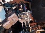
Picture number 1 shows where the abs pc board is located, yes inside that shiny metal box where it says abs ecm
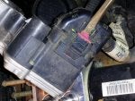
Pic Number 2: To get this connection off you have to use a screw driver and pry out on it and down away from the unit at the same time(The pink clip looking thingy), then once it release's you can push in on the retention plastic prongs and it comes off.
Pic Number 3: I know it is hard to see but where I drew the red circles on this box, those are the six screws I removed (4 outside of the pump piston box and 2 inside the pump piston box.)
Pic Number 4: What I have circled in red here is where I did the repairs with some flux and solder.
Notes: It is a real pain in the arse to get this cover off of the brain box. How I did it was use a razor knife and carefully cut around all the corners of the edge just enough to penitrate but not to deep as to destroy the PC board inside. It took me about an hour to get this cover off( Hey I was being carefull!!!) Once it starts to become lose you will know but it fights ya all the way till the end. Also I highly recomend a magnifying glass (I used my magnifier app on my phone for it was hard for me to see that small) Um as for sealer to seal the unit back up , I used Permatex Ultra Black RTV High heat silicone gasket maker(yes the very same kind i used on my timing chain cover,oil pan,etc..). It has to be able to take heat and still remain sealed. Also the tools need to get the unit off of the pump body was(4 screws) : T20 star bit torque socket (mine were on pretty tight and a little rusted) and to get the 6 screws out of my unit in order to pry the silver cover off to expose the PC board: T8 star torque driver ( looks like a screw driver but very small.) I know these pictures arent the greatest but it was later at night working on this.Anyone more question, feel free to ask, Im working all day today so I will do my best to get back.
Attachments
-
61.6 KB Views: 5,415
-
77.8 KB Views: 4,075
-
93.3 KB Views: 3,428
-
97.2 KB Views: 3,127
157 posts
·
Joined 2010
I'm going to have to add to my thread to better prepare people on what the are getting into. I was angry and fed up with 6 months of that light being unpredictable so I used a #2 flathead screwdriver and a hammer to get the metal cover off but I was gentle of course.
After you attempted to fix it did you clear the codes? Did you look for any darker brown or black burns in the unit and on the connections/connectors?
Also is your brake fluid old or really dirty? I read it's common for air to get trapped in the abs so I would think if the motor is spinning in air bubbles it could read that it isn't working properly (Just a random idea)
The pump is an electric motor so you can test it...
As codes are just to point a macanic in the right direction...electric motors rarely fail and this one is sealed and the abs is only active in hard braking so this motor is rarely used.
Your code says "Electronic Brake Control Module Motor Relay Circuit" I didn't look at mine that close but can you see the relay? It should be a black or blue box on the board. You should be able to test that relay while it is on the board and see if it works properly I would assume it is a sealed relay so you can't break it open so see it working. I would say the unit already throws codes so don't be afraid to poke at it (with caution of course).
Sorry my solution didn't work out for you but I still believe you can fix it with a little more troubleshooting.
157 posts
·
Joined 2010
I really think we can figure this out or at least find out if your code is one that other should attempt to fix themselves. I am going to pull off my abs module again and see if I can find the pump motor relay and test it. I'll let you know what I find.
157 posts
·
Joined 2010
So I have disassembled and desoldered my ABS unit I will have pictures and a full description of how you will be able to test that relay by the morning. The relay is fairly simple it looks like a 16v 10amp spst relay and I found it for $1.72 + $2.80 shipping (that's a matching part number relay) so lets hope your relay is what is causing your problem. My camera battery died but I should have it all posted in the morning.
code_red63366
Discussion starter
620 posts
·
Joined 2011
Sounds good Alan,,, Yes I did attempt to clear the code but it wouldnt let me. No noticable burns on the unit or connectors however I didnt look hard enough at them umm my brake fluid is normal looking, just change the rear brakes out last weekend. As for air being trapped in the unit itself? I have no idea how to figure that out or how to even go about testing it/ I just have a steady non stop abs and brake light on now compared to before when it flickered on and off. I dont know where the motor relay is on it, i thought it may have been on the outside of the brain box? And look foward to your instructions on disassemble on checking the relay. Yes it would be nice to get it fixed, after all I have been driving with it like that now for 3 years.
157 posts
·
Joined 2010
Ok I really hope it is your relay.
Getting the unit repaired by a qualified technician will cost anywhere from $95 to $200 and buying a used unit costs around $150 and up. (Those numbers reflect what I have found but I’m sure others have found better deals)
I find it rare for electrical parts to go bad without some type of abusive heat where the relay is mechanical meaning it has moving parts and of course the contacts in the relay can get dirty, pitted, or just not get good contact. So lets test it.
Note: I am no professional nor am I trained for this. I'm just a 24 year old guy who likes to tear things apart and rebuild them to test and improve my skills but I find my research skills allow me to make any qualifying piece of paper unnecessary.
2nd Note: if your ABS looks to be the same as mine then you can skip down to the relay testing part and skip the disassembly. You really only need to disassemble the unit if the relay tests bad but I had to disassemble it to get the part number off the relay to lookup the datasheet.
It took me about 45min to desolder and take apart the ABS unit. It is difficult and in the pictures you can see why.
So here are the tools I used. I had a 40watt soldering iron and I strongly recommend a smaller tip than the one I used also I used a bulb vacuum desoldering tool (that red thing) to suck the solder off the board. This bulb had a large tip which made it hard to get into the small spaces. I would recommend a different one with a smaller tip to get into the tight spaces.
![Image]()
Taking off the board is a challenge. You have to take off all the extra solder on all the spots where one of the connectors connects to the board and where the solenoids connect to the board. I had to unsolder the solenoids because the were blocked off.
![Image]()
![Image]()
The case was blocking them.
![Image]()
Then you apply a little upward pressure, I used a screw driver, then you just move around heating up the connections one by one slowly allowing the board to separate from the plastic case. Sounds hard but fairly easy with patience (it's a slow process).
![Image]()
This was the hardest spot.
![Image]()
So I got a little rough and had a small mishap but all is good I just glued it back down and when I reassemble it will be just fine. So take you time.
![Image]()
This is everything separated.
![Image]()
So here is what we were looking for, the relay.
![Image]()
So I typed "JSM1-12v-5-H38 datasheet" into google and found the datasheet.
This is an automotive 12v high capacity 15A relay with a 6.3 volt pick-up meaning you need at least 6.3 volts to actuate it. (I used a 9 volt battery)
This is what the datasheet revealed.
![Image]()
![Image]()
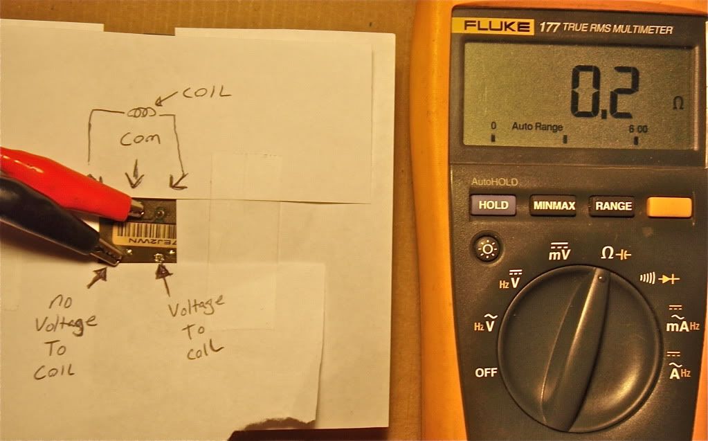
I don't know how familiar you are with relays but from the datasheet you should be able to figure out how to test it. Just test for continuity from the com to the no voltage side and then apply 9v to the coils and test for continuity from the com to the voltage side. This picture is me testing the no voltage side with my multimeter. I didn't have enough jumpers to take a pic of me testing the power side with voltage applied but mine tested good.
![Image]()
Getting the unit repaired by a qualified technician will cost anywhere from $95 to $200 and buying a used unit costs around $150 and up. (Those numbers reflect what I have found but I’m sure others have found better deals)
I find it rare for electrical parts to go bad without some type of abusive heat where the relay is mechanical meaning it has moving parts and of course the contacts in the relay can get dirty, pitted, or just not get good contact. So lets test it.
Note: I am no professional nor am I trained for this. I'm just a 24 year old guy who likes to tear things apart and rebuild them to test and improve my skills but I find my research skills allow me to make any qualifying piece of paper unnecessary.
2nd Note: if your ABS looks to be the same as mine then you can skip down to the relay testing part and skip the disassembly. You really only need to disassemble the unit if the relay tests bad but I had to disassemble it to get the part number off the relay to lookup the datasheet.
It took me about 45min to desolder and take apart the ABS unit. It is difficult and in the pictures you can see why.
So here are the tools I used. I had a 40watt soldering iron and I strongly recommend a smaller tip than the one I used also I used a bulb vacuum desoldering tool (that red thing) to suck the solder off the board. This bulb had a large tip which made it hard to get into the small spaces. I would recommend a different one with a smaller tip to get into the tight spaces.

Taking off the board is a challenge. You have to take off all the extra solder on all the spots where one of the connectors connects to the board and where the solenoids connect to the board. I had to unsolder the solenoids because the were blocked off.

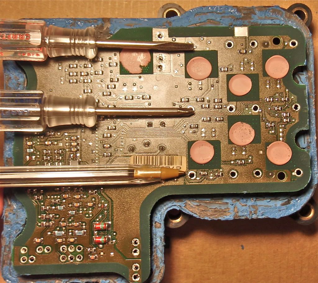
The case was blocking them.

Then you apply a little upward pressure, I used a screw driver, then you just move around heating up the connections one by one slowly allowing the board to separate from the plastic case. Sounds hard but fairly easy with patience (it's a slow process).

This was the hardest spot.

So I got a little rough and had a small mishap but all is good I just glued it back down and when I reassemble it will be just fine. So take you time.

This is everything separated.
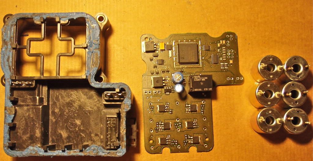
So here is what we were looking for, the relay.
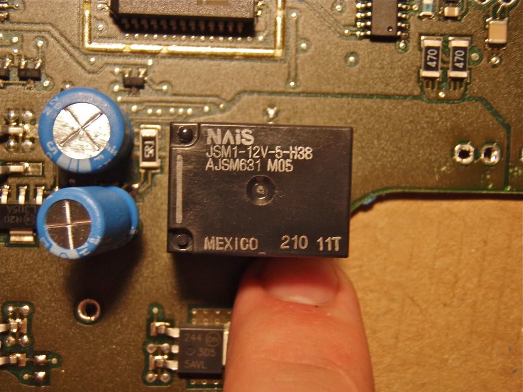
So I typed "JSM1-12v-5-H38 datasheet" into google and found the datasheet.
This is an automotive 12v high capacity 15A relay with a 6.3 volt pick-up meaning you need at least 6.3 volts to actuate it. (I used a 9 volt battery)
This is what the datasheet revealed.

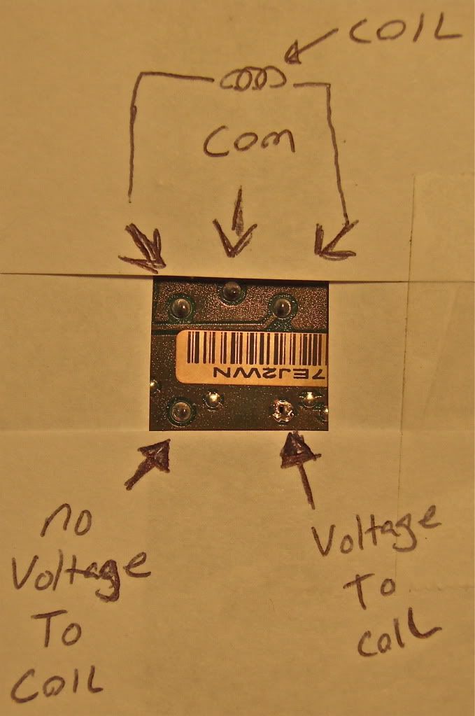
I don't know how familiar you are with relays but from the datasheet you should be able to figure out how to test it. Just test for continuity from the com to the no voltage side and then apply 9v to the coils and test for continuity from the com to the voltage side. This picture is me testing the no voltage side with my multimeter. I didn't have enough jumpers to take a pic of me testing the power side with voltage applied but mine tested good.
157 posts
·
Joined 2010
Their is always the possibility that the relay tests good but, when in use, it sometimes works and other times it doesn't or their is an unlikely electrical issue we can't test ourselves. The options are really up to you. It has been broken for 3 years so to spend $5 for a new relay to maybe have it fixed or $150 for a used unit? I would opt for the $5 test and if it doesn't work you lose $5 +the cost of new tools and a few hours of your free time but if you fix it with a new relay the feeling of accomplishment will outweigh all the frustration in the troubleshooting process. Plus you will learn alot. You will definitely know next time something like this happens you will troubleshoot it yourself or pay someone to do it.
-
?
-
?
-
?
-
?
-
?
-
?
-
?
-
?
-
?
-
?
-
?
-
?
-
?
-
?
-
?
-
?
-
?
-
?
-
?
-
?
- posts
- 8.9M
- members
- 200K
- Since
- 2001
S10forum is the community to discuss the S-Series, Chevrolet Colorado and GMC Canyon. Join to discuss rebuilds, modifications, tech articles and more!
Explore Our Forums

![20120504_220704[1].jpg](/d1/attachments/101/101097-48480750d03e7e3abe383f16b1170cdc.jpg)
![20120504_220603[1].jpg](/d1/attachments/101/101122-cccc3981d148a76a5d7c86f7a34e509b.jpg)
![20120504_203612[1].jpg](/d1/attachments/101/101146-4b115260bd32485974781bfa14680a2f.jpg)
![20120504_203606[1].jpg](/d1/attachments/101/101168-a13d500b021833876a1c581afee74f2e.jpg)
