S-10 Forum banner
21 - 40 of 62 Posts
Discussion starter · #21 · (Edited)
Picture number 1 shows where the abs pc board is located, yes inside that shiny metal box where it says abs ecm
Pic Number 2: To get this connection off you have to use a screw driver and pry out on it and down away from the unit at the same time(The pink clip looking thingy), then once it release's you can push in on the retention plastic prongs and it comes off.
Pic Number 3: I know it is hard to see but where I drew the red circles on this box, those are the six screws I removed (4 outside of the pump piston box and 2 inside the pump piston box.)
Pic Number 4: What I have circled in red here is where I did the repairs with some flux and solder.

Notes: It is a real pain in the arse to get this cover off of the brain box. How I did it was use a razor knife and carefully cut around all the corners of the edge just enough to penitrate but not to deep as to destroy the PC board inside. It took me about an hour to get this cover off( Hey I was being carefull!!!) Once it starts to become lose you will know but it fights ya all the way till the end. Also I highly recomend a magnifying glass (I used my magnifier app on my phone for it was hard for me to see that small) Um as for sealer to seal the unit back up , I used Permatex Ultra Black RTV High heat silicone gasket maker(yes the very same kind i used on my timing chain cover,oil pan,etc..). It has to be able to take heat and still remain sealed. Also the tools need to get the unit off of the pump body was(4 screws) : T20 star bit torque socket (mine were on pretty tight and a little rusted) and to get the 6 screws out of my unit in order to pry the silver cover off to expose the PC board: T8 star torque driver ( looks like a screw driver but very small.) I know these pictures arent the greatest but it was later at night working on this.Anyone more question, feel free to ask, Im working all day today so I will do my best to get back.
 

Attachments

I'm going to have to add to my thread to better prepare people on what the are getting into. I was angry and fed up with 6 months of that light being unpredictable so I used a #2 flathead screwdriver and a hammer to get the metal cover off but I was gentle of course.

After you attempted to fix it did you clear the codes? Did you look for any darker brown or black burns in the unit and on the connections/connectors?
Also is your brake fluid old or really dirty? I read it's common for air to get trapped in the abs so I would think if the motor is spinning in air bubbles it could read that it isn't working properly (Just a random idea)

The pump is an electric motor so you can test it...
As codes are just to point a macanic in the right direction...electric motors rarely fail and this one is sealed and the abs is only active in hard braking so this motor is rarely used.

Your code says "Electronic Brake Control Module Motor Relay Circuit" I didn't look at mine that close but can you see the relay? It should be a black or blue box on the board. You should be able to test that relay while it is on the board and see if it works properly I would assume it is a sealed relay so you can't break it open so see it working. I would say the unit already throws codes so don't be afraid to poke at it (with caution of course).

Sorry my solution didn't work out for you but I still believe you can fix it with a little more troubleshooting.
 
So I have disassembled and desoldered my ABS unit I will have pictures and a full description of how you will be able to test that relay by the morning. The relay is fairly simple it looks like a 16v 10amp spst relay and I found it for $1.72 + $2.80 shipping (that's a matching part number relay) so lets hope your relay is what is causing your problem. My camera battery died but I should have it all posted in the morning.
 
Discussion starter · #25 ·
Sounds good Alan,,, Yes I did attempt to clear the code but it wouldnt let me. No noticable burns on the unit or connectors however I didnt look hard enough at them umm my brake fluid is normal looking, just change the rear brakes out last weekend. As for air being trapped in the unit itself? I have no idea how to figure that out or how to even go about testing it/ I just have a steady non stop abs and brake light on now compared to before when it flickered on and off. I dont know where the motor relay is on it, i thought it may have been on the outside of the brain box? And look foward to your instructions on disassemble on checking the relay. Yes it would be nice to get it fixed, after all I have been driving with it like that now for 3 years.
 
Ok I really hope it is your relay.

Getting the unit repaired by a qualified technician will cost anywhere from $95 to $200 and buying a used unit costs around $150 and up. (Those numbers reflect what I have found but I’m sure others have found better deals)

I find it rare for electrical parts to go bad without some type of abusive heat where the relay is mechanical meaning it has moving parts and of course the contacts in the relay can get dirty, pitted, or just not get good contact. So lets test it.

Note: I am no professional nor am I trained for this. I'm just a 24 year old guy who likes to tear things apart and rebuild them to test and improve my skills but I find my research skills allow me to make any qualifying piece of paper unnecessary.

2nd Note: if your ABS looks to be the same as mine then you can skip down to the relay testing part and skip the disassembly. You really only need to disassemble the unit if the relay tests bad but I had to disassemble it to get the part number off the relay to lookup the datasheet.

It took me about 45min to desolder and take apart the ABS unit. It is difficult and in the pictures you can see why.

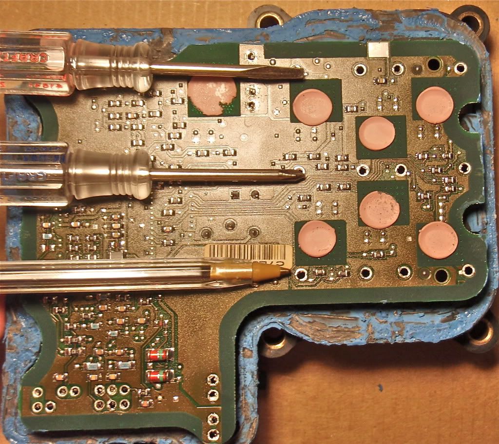
So here are the tools I used. I had a 40watt soldering iron and I strongly recommend a smaller tip than the one I used also I used a bulb vacuum desoldering tool (that red thing) to suck the solder off the board. This bulb had a large tip which made it hard to get into the small spaces. I would recommend a different one with a smaller tip to get into the tight spaces.

Image


Taking off the board is a challenge. You have to take off all the extra solder on all the spots where one of the connectors connects to the board and where the solenoids connect to the board. I had to unsolder the solenoids because the were blocked off.

Image

Image

The case was blocking them.
Image


Then you apply a little upward pressure, I used a screw driver, then you just move around heating up the connections one by one slowly allowing the board to separate from the plastic case. Sounds hard but fairly easy with patience (it's a slow process).

Image


This was the hardest spot.

Image


So I got a little rough and had a small mishap but all is good I just glued it back down and when I reassemble it will be just fine. So take you time.

Image


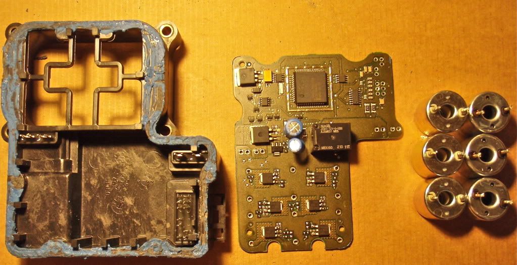
This is everything separated.

Image


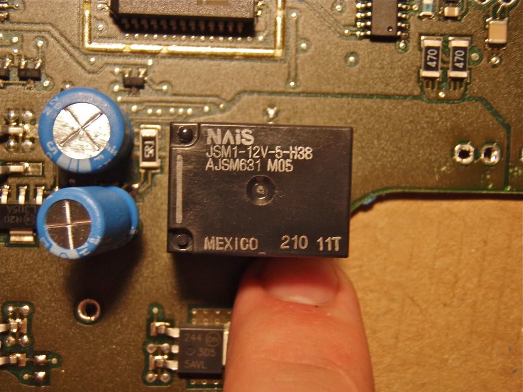
So here is what we were looking for, the relay.

Image


So I typed "JSM1-12v-5-H38 datasheet" into google and found the datasheet.
This is an automotive 12v high capacity 15A relay with a 6.3 volt pick-up meaning you need at least 6.3 volts to actuate it. (I used a 9 volt battery)

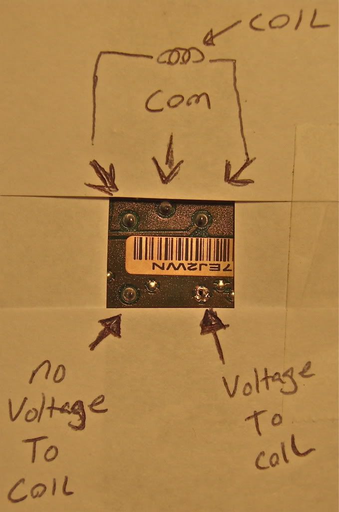
This is what the datasheet revealed.

Image

Image


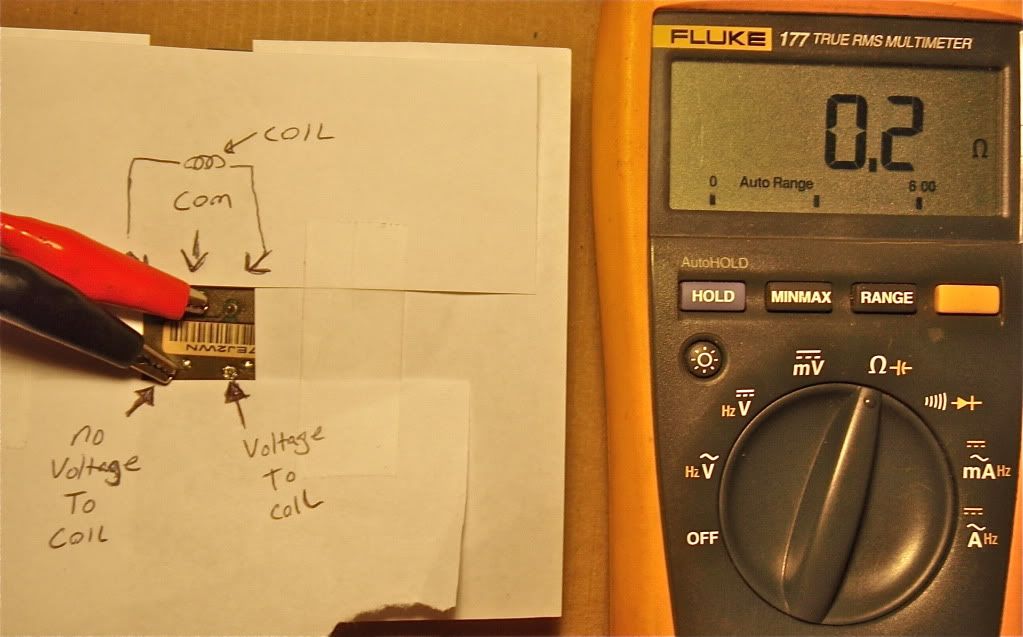
I don't know how familiar you are with relays but from the datasheet you should be able to figure out how to test it. Just test for continuity from the com to the no voltage side and then apply 9v to the coils and test for continuity from the com to the voltage side. This picture is me testing the no voltage side with my multimeter. I didn't have enough jumpers to take a pic of me testing the power side with voltage applied but mine tested good.

Image
 
Their is always the possibility that the relay tests good but, when in use, it sometimes works and other times it doesn't or their is an unlikely electrical issue we can't test ourselves. The options are really up to you. It has been broken for 3 years so to spend $5 for a new relay to maybe have it fixed or $150 for a used unit? I would opt for the $5 test and if it doesn't work you lose $5 +the cost of new tools and a few hours of your free time but if you fix it with a new relay the feeling of accomplishment will outweigh all the frustration in the troubleshooting process. Plus you will learn alot. You will definitely know next time something like this happens you will troubleshoot it yourself or pay someone to do it.
 
Also, I don't know exactly what those two blue capacitors go to but capacitors do wear out so if you do decide to replace the relay also replace the capacitors too. One might be to power the motor during startup and restart where the motor is requiring more amps. If the motor isn't getting enough power on startup and restart it will heat up everything which may be why my solder connections cracked?
 
Discussion starter · #29 ·
Wow! well done Alan,, sure I dont mind giving it a shot but gotta get a better soldering iron 1st along with a few other things. I use to build PC boards for a company called haywrap in my teens. My biggest prob I had was when it came to repairig a board, it was hard not to burn the board in some form or another,, of course a smaller soldering gun and some good magnifying glasses would cure that and I didnt have that. If there was a bad circuit run, we simply just used a wire and jumped between it then soldered it on. I didnt get into the parts detailed as much as my boss was. But there is a 1st time for everything. Most folks are at a loss when it comes to messing with wiring due to the danger issues that can result as fire and this is what keeps most of us at bay.I have learned a few things about starting electrical fires, safety is always important. So with that being said, yeah your right , if you dont feel comfortable with doing this fix than leave it to a pro and spend the 150 bucks or so .. as for me? Im gonna go for it when I get some free time, plus i plan on having a back up 1st since the truck is my daily driver just incase I screw it up, hek what would it hurt to learn something new. Wiring has always been my down fall when it comes to cars/trucks and it's time to change that. When I take it on I will get ahold of ya,, check your friends request on here.. peace brother!
 
I am really looking forward to hearing about your result. I would like to add this information to my sticky thread to help others. I don't think you need a backup module I would wait for the results, I drove my truck around yesterday and this morning without the module on it (probably around 30 miles). The ABS light is on but the truck stops with no problems and that modulemaster site says it's ok to drive without a module.
 
Discussion starter · #31 ·
Your right about being able to run the truck with the module off it as long as the pump box is protected with some sort of covering,, even the GM expert tech's say the same thing... I was reading up on another site on this and there is a diagnose's i did not perform that Im thinking would be a good idea since it is easy to do. They told me to check the fuse and main fat red wire feed to the unit, which I did (even though they insisted it wont always throw a abs light) both looked fine. However another thing they suggested performing was adding voltage to the actual pump itself,, (yeah Im sure you mentioned this somewhere in one of your comments, duh!) but I have yet to have done it. If I hook up power to it and it runs the abs, then the GM expert tech says it is definitely inside my module (aka: brain)which is probably what you have been trying to explain to me all along here. Figure i will do this test just to be sure 1st and then go your route and tear into it again, after aquiring the proper tools, minus the abs unit back up, hek worse comes to worse i will scramble some money up for a rebuilt one... maybe sometime this week or next wekend (I work 2 jobs so I am contantly busy and rarely have time to work on the truck unless i play hooky).
 
Discussion starter · #32 ·
Alan, was able to sneak in some time this afternoon and test that motor on the abs box. Im hoping I did it right. I hooked on to the postitive side of fuse box under the hood, unplugged the motor connector (2 wire,black and red) and put some power into the red side of that connector. tried it without the ign on and with ign on. It did nothing. no noise, no vibration or moment. So with that being said, im guessing that the motor itself is no good? Im pretty sure I done it right( done a few test like this in the past before)??
 
Discussion starter · #34 ·
I thought about that and went back out and tried that,,,,,still nothing.
Even used a test light to make sure I had power..... I did.
 
If you hooked up power to the motor and it didn't do anything then you have your problem. I wish it was a cheaper fix, I wonder if you can just replace the motor itself? Changing out the entire pump valve block is a pain with all the bleeding you would have to do. I still have my module off so I'm going to go test my pump motor later today or tomorrow and see what it does.
 
Discussion starter · #36 ·
If you hooked up power to the motor and it didn't do anything then you have your problem. I wish it was a cheaper fix, I wonder if you can just replace the motor itself? Changing out the entire pump valve block is a pain with all the bleeding you would have to do. I still have my module off so I'm going to go test my pump motor later today or tomorrow and see what it does.
Alan,, I brain farted here, I didnt have a good ground like i thought I did. I just went outside and took a test light with me to make sure all my connections were good and they were, then I added power and ground to the motor and it worked. Apparently I did not have a good ground from the other day. So the pump motor does work. I took the liberty of taking the unit off the truck also and I covered the connector wires and unit itself from the elements. Next.... go back into the box..
 
All my suspicions on the DIY fix so far have been correct, I like that. Knowing what we know so far, I'm fairly sure it is your relay on the board. I am definitely looking forward to you switching it out.

I don't know if your relay will be the same as mine so make sure before you order one that you check the one on your board. It was easy to find mine online and the relay price in post #24 is accurate.
 
Discussion starter · #38 ·
Hopefully I will get some free time here soon to pull that apart and replace it.Im sure there is a way to test those but why bother when the replacement part isnt all that much, I just hope it works.
 
Discussion starter · #40 ·
Also, I don't know exactly what those two blue capacitors go to but capacitors do wear out so if you do decide to replace the relay also replace the capacitors too. One might be to power the motor during startup and restart where the motor is requiring more amps. If the motor isn't getting enough power on startup and restart it will heat up everything which may be why my solder connections cracked?
I was told last night by the dudes at radio shack that the way you tell is they are bad other than testing the capacitors is by a visual. the top part of them (silver part) will be swelled up along with possibly the side. Mine were fine , not sure on the relay as I have yet to figure out how to test the volatge side. Working on getting a used module now since the old module board is toast, thanks in part to me. Posting pictures.
 
21 - 40 of 62 Posts